Lesson 4 · 6 min
Hydraulic symbols explained: how to read an ISO 1219 diagram
A hydraulic diagram is drawn with a small set of standard shapes: circles for pumps and motors, squares for valves, rectangles for cylinders. Learn twelve and you can read most machine schematics.
Start here
The 2-minute primer
New to this? These 6 cards explain the lesson in plain words. Go through them first and the lesson will make sense.
Primer done.
-
1/6Picture this
Road signs, not photographs
A road sign doesn’t show a photo of the road ahead. A triangle warns, a circle gives an order, and a few simple marks tell you what to expect.
Hydraulic drawings work the same way. Each shape tells you what a part does, not what it looks like. Learn the shapes once and you can read almost any drawing.
-
2/6The big idea
A few shapes describe any machine
Every hydraulic machine comes with a circuit diagram. It uses a small set of standard shapes: circles for pumps and motors, squares for valves, long rectangles for cylinders.
Once you know them, the drawing reads like a map. Follow the line from the pump, through each valve, to the cylinder and back to the tank.
-
3/6Words you'll meet
Five words, in plain English
- Schematic
- a drawing of a hydraulic machine made of symbols, showing how the oil travels between parts.
- ISO 1219
- the international standard that sets out the hydraulic symbols and how diagrams are drawn.
- Port
- a connection where oil enters or leaves a part, marked with letters such as P, T, A and B.
- Pilot line
- a thin control line, drawn dashed, carrying a small oil signal that works a valve.
- 4/3 valve
- a valve with four ports and three positions, drawn as three squares side by side.
-
4/6Why it matters
The drawing is the map to a fault
When a machine misbehaves, the diagram is the fastest way to see what it should be doing. Without it, people guess and swap parts.
Someone who can read it can trace the oil from the pump to the cylinder that is playing up, find the valves that hold the load, and know where a gauge should go.
-
5/6In this lesson
What you’ll be able to do
- Recognise pumps, motors, valves and cylinders by their shape.
- Read a valve’s squares to see where oil goes in each position.
- Tell main lines, pilot lines and drain lines apart.
- Follow a real drawing from the pump to each cylinder.
-
6/6Quick check
On a drawing, what does a circle show?
Right: circles are things that turn. A small triangle shows whether oil is pushed out (a pump) or drives it round (a motor).
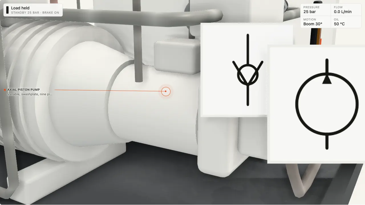
Every hydraulic machine comes with a circuit diagram, and the diagram is the fastest way to understand what the machine should be doing when it isn’t. The symbols look cryptic at first, but there are only a few building blocks, and they follow a logic. Pick a symbol in the animation to see the real part it stands for, then switch to “Test yourself” and find them without the names.
In simple terms
The symbols don’t show what a part looks like. They show what it does.
- Circles are things that turn. A pump or a motor. A small black triangle shows which way the oil goes: pointing out of the circle means oil is pushed out (a pump), pointing in means oil drives it round (a motor). An arrow drawn across means its size per turn can be changed.
- Squares are valves. One square for each position the valve can be in. Arrows inside show where oil can go in that position; a T shape means “blocked”. A directional valve with three squares has three positions, usually “one way”, “hold” and “the other way”.
- Long rectangles are cylinders. A line across is the piston, a line coming out is the rod. One port means oil pushes one way only; two ports means it can push both ways.
- Zigzags are springs, dashed lines are pilot lines (small control signals of oil pressure) and solid lines are the main oil lines.
- A diamond is something that treats the oil: a filter, a cooler or a heater, depending on what’s drawn inside.
Once you know these, a schematic reads like a map. Follow the line from the pump, through each valve, to the cylinder or motor, and back to the tank.
- Play with it: Twelve ISO 1219 symbols; pick one and the real part beside it works. Then test yourself.
Sign in to read the rest of this lesson
Continue reading
Save your progress, open all 115 lessons and get a Course completed card when you finish.
or use your email
In the rest of this lesson
- Interactive animation: ISO 1219 symbols and the parts behind them
- For engineers
- Deep dive
- Key numbers
- 4 questions people ask
- Quiz: 4 questions
- Ask our engineers about this lesson
Familiarisation training from Al Safwan Academy. Finishing a course shows completion of online familiarisation training: it is not an STCW, flag-approved or manufacturer qualification, and these courses don't replace that training. The manufacturer's manual and your flag's rules always come first.